

DBC
-
Content Count
9 -
Joined
-
Last visited
Posts posted by DBC
-
-
On 5/15/2019 at 7:42 AM, tomcctv said:Your service cable will fit the full cnb ranger including HD analog
i have 100s of them out ..... even profile picture is the same cam and that’s been there since I joined.
Now that it’s apart you can see why I suggested doing settings at night
Thank you Tom, I have now installed the Concept Pro VLP5026 and the Concept Pro AIR4026 please see the print screen below “cameras 7 & 8”, although I still need to set up the VLP5026 at night time like you said Tom.
Tom would you or anyone else have a spare "square" Service Video Output Connector for a Concept Pro AIR4026 camera please as it uses a "square" connector not an oblong connector?
I already have a Service Video Output connector for the VLP5026 and I also have an OSD Connector for the AIR4526HGE / 4527HGE / 5026HGE range but they are both sadly different.
Camera 7 Concept Pro AIR4026 Camera 8 Concept Pro VLP5026
These are the two Service Video Output connectors that I alraedy heave but they do not fit the square connector on the Concept Pro AIR4026
-
1 hour ago, Cyn said:Would it make the connection longer? It just might be worth a try since like you said they are cheap! Thank I will try it.
Yeah just to make it stick out further than the other connectors, I have never seen the tool so I don't know if it will fit.

-
On 7/3/2019 at 3:16 AM, Cyn said:The problem with my Swann camera inputs is that they have a fat thick cable instead of a smooth coax cable. I have 2 of the BNC tools one short and one middle length and neither one will fit over the thick cable to reach the metal connectors that turn. Any suggestions for a different tool. I have used the tools for years at Telco on BNC connectors and have not had this problem!
Would it help to add a BNC Male to Male connector, they only cost a £1.00 or so if it doesn't work?

-
I managed to get hold of a PDF Instruction / Manual file today, as far as I can see the camera is already set to default as I think that my camera is the Hybrid version.
-
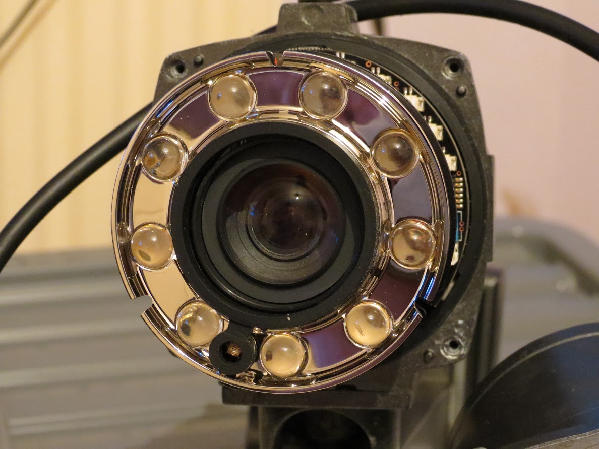
Thank you tomcctv, I would not have had the confidence to take the lens cap of judging by the quality of a Concept Pro AIR4526HGE .
The build quality on this 11yr old Concept Pro VLP5026 is a lot better, I am now thinking that my Service Video Output Cable from a Concept Pro VVP9324DN will connect to the Concept Pro VLP5026 so that I can view the OSD on a monitor.
-
Thank you very much for the helpful reply tomcctv, I will have a go later and let you know how I get on.
Do you know what the Brown and Green wires are for?
I have a spare DVR set up for testing so I can set up the camera at night before installing it.
I had thought about taking the camera apart myself but I had concerns as the camera that had let the water in was a Concept Pro AIR4526HGE and all I had done was add the Concept Pro AIR-IR lamps and the water got in through the Concept Pro AIR-IR mount after only about a years use.
I was also concerned that if I open up the factory seal on the Concept Pro VLP5026 that it may also let water in if I am not careful, plus I am not that confident that the cameras can cope with being opened.
Sadly Concept Pro won't deal with home owners if there kit isn't fitted by an authorised fitter, if I knew the equivalent CNB tech part number I could look for a PDF Instruction manual on Google.
I also know that the instruction manuals are not a lot of help but it may tell me what the two other wires are for although the instruction manual for a Concept Pro AIR4526HGE has is incorrect coloured wiring diagram.
-
These are the connections on a Concept Pro AIR701-IRH which can be controlled by a RS485 Connector cable, this is why I am guessing that the Concept Pro VLP5026 may be able to be controlled by a Concept Pro VA-KBDPRO+ using RS-485 data
Concept Pro AIR701-IRH wiring instructions
Concept Pro AIR701-IRH connector wires
Concept Pro AIR701-IRH camera
-
I have a Concept Pro VXM4/8 DVR analogue system running on my home with eight cameras and I have recently had an issue with water getting in one of the cameras so I am trying to replace the camera with a Concept Pro VLP5026.
Doe's anyone have an instruction manual available for a VLP5026, or any camera from the VLP range please i.e. the VLP4026 or a VLP4526?
The cameras are about 10 years old now so I don't hold a lot of hope that anyone will have a PDF instruction file available.
I basically need to know how I can adjust the camera lens please.
I have read a data sheet that says that only the VLP4026 has External Lens Adjustment, I have found the following data sheet for the VLP5026 but I do not know if is possible to control the camera via a Concept Pro VA-KBDPRO+ using RS-485 data.
The camera has six wires and I know what four are used for as I already have the camera working, I just don’t know what the other two wires are for.
Doe’s anyone know what the other two wires are for, i.e. are they used for the RS-485 data?
If the other two wires are for RS-485 data does that mean I will be able to adjust the lens via a Concept Pro VA-KBDPRO+ using RS-485 data?
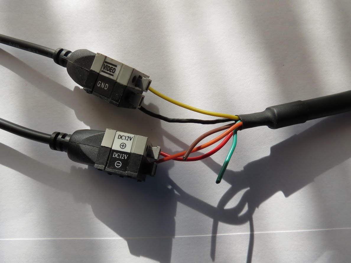
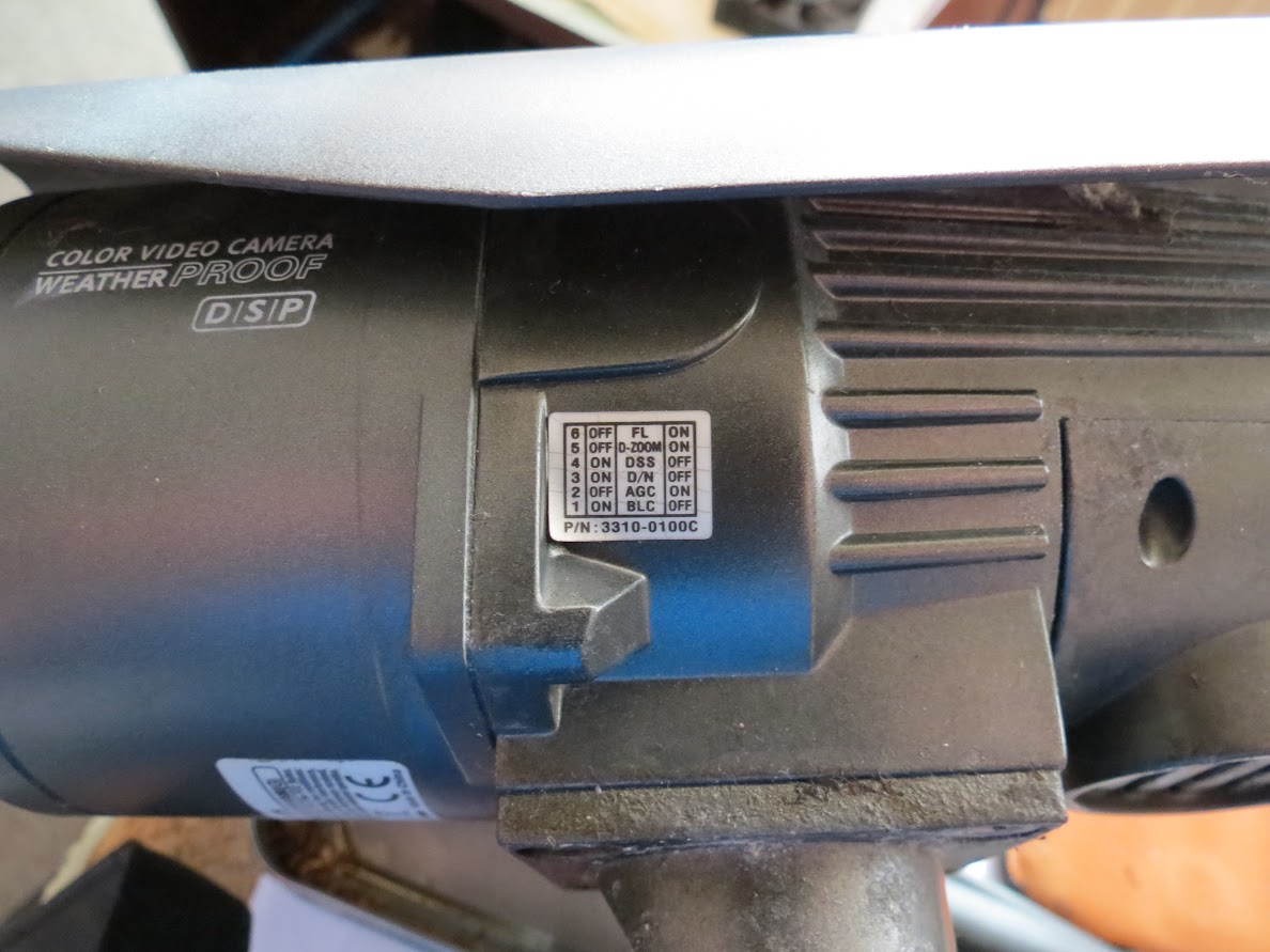
The data sheet says that the VLP5026 has Service Video Output, I have only ever adjusted the settings on a Concept Pro CVP9324DNIR by attaching a Service Video Output to the camera and then viewing the data on a dedicated monitor.
As far as I can tell the VLP5026 doesn’t have any where to plug in a Service Video Output although I could be wrong.Any help would be gratefully received, thank you in advance.
VLP5026 Data sheet
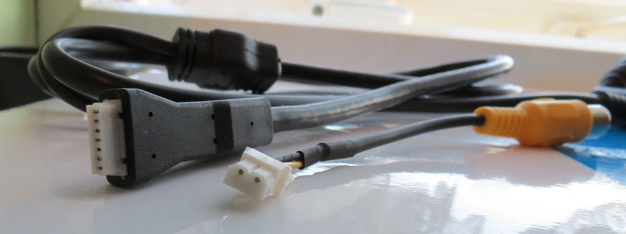
12V DC Power supply connectors
The six wire connectors are Yellow video and Black ground, power DC12V + Red and DC12V - Orange.
The two other wires which I don not know what they are for are Brown and Green.
Service Video Output instructions printed on the side of the camera
Service Video Output instructions zoomed in
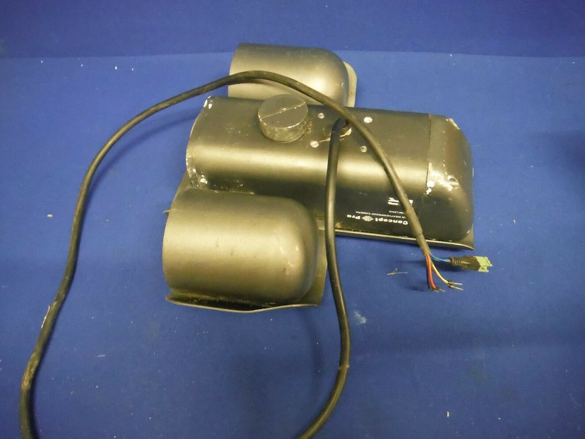
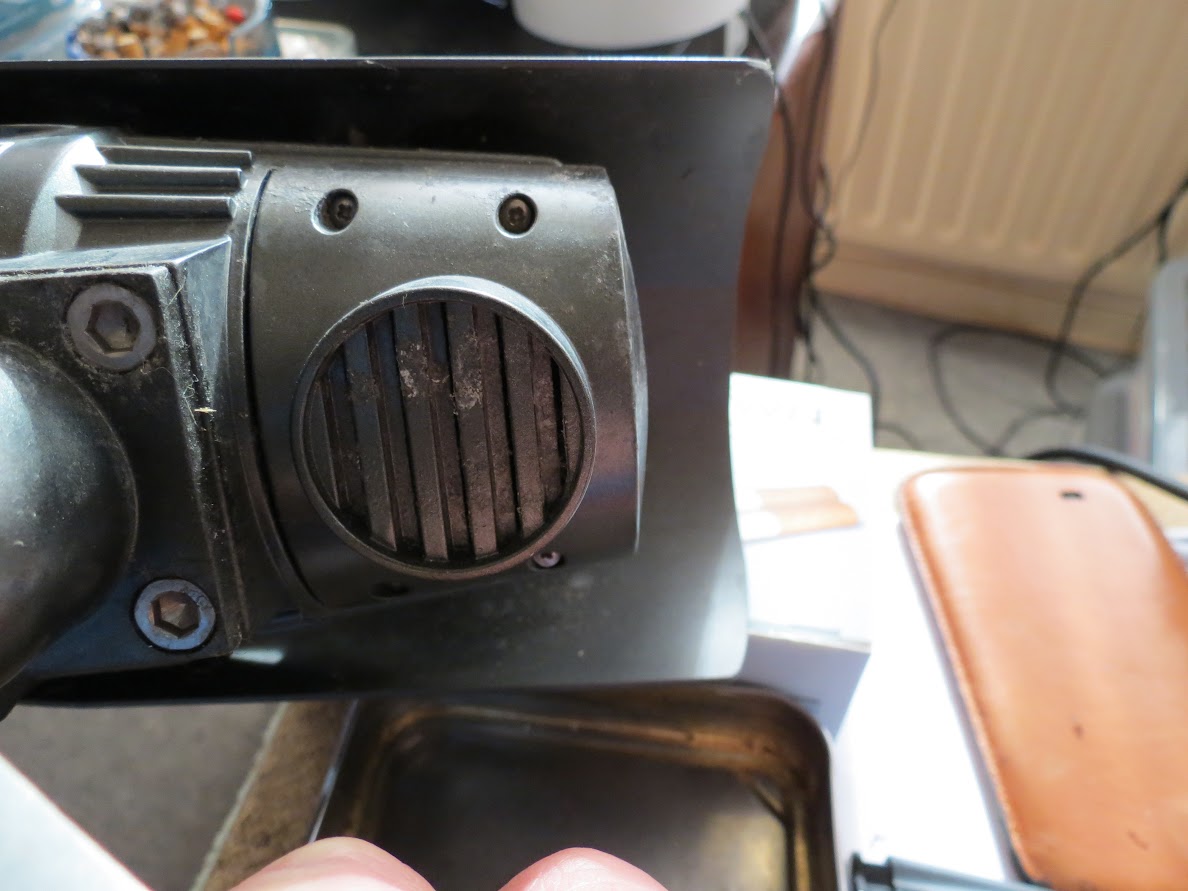
Built in heater and blower on the rear of the camera


Concept Pro VLP5026 Camera instruction file needed
in General Analog CCTV Discussion
Posted
Thank you, I will pm now.