

the toss
-
Content Count
977 -
Joined
-
Last visited
Posts posted by the toss
-
-
Well since they are 24Vac cameras you would be best off using a 24Vac adapter. A multi output power supply is a whole lot neater.
-
Not that I'm aware of. We don't care much about peoples religion in Aust. You'll have to enlighten me yourself
-
How does this compare to your day time performance? I am surprised the pic is still B/W with two 400W halogens operating. While the specs for your camera say 0 lux there is no measure of how well it operates at 0 lux. The back focus is the focal length between the lens & the image sensor. On full body cameras there is a lock screw which allows the lens mounting flange to be adjusted. On most dome there is also a lock screw that retains the lens assembly on to the camera. I have never had to do the back focus on a dome so I don't know how difficult it is.
I have never had a bullet camera apart so I can't help there either. Google "back focus" for an explaination of how to do it. You will need a neutral density filter or a number 5 welding goggle glass to simulate low ligh conditions.
What was it you did to improve the focus so far ?
-
I'd still be interested to know where & how much they cost. I've been building electronics since I was 10 so soldering is as easy as breathing. I have a mate who has been welding since he was 12. His welds look like they have been applied with a caulking gun they are just SOoo neat. There is nothing he can't do with metal - BUT he cant solder. Its funny what you take for granted. I dont use an expensive iron. A 60W adjustable with changeable tips is all you need unless you are going to play with SMD (surface mount device) componentry. I have had a go but my hand is not steady enough & my eyes are not good enough so I stick to discreet components.
-
The bright spot is inherent to most IR cameras. With your halogen floodlight installed you shouldn't need to go IR at all. A decent low light cam will give excellent results & maintain the colour if that is important to you. If it is not then go for a B/W camera which has far superior low light performance. If you need to stay with the IR option then disconnect the IR at the camera & install remote IR illuminators (dirt cheap from China) to give more consistant lighting.
The image you post seems to be terribly out of focus. If it were a full body camera I would say you need to adjust the back focus but I'm pretty sure that is not an option with domes & bullets
-
I am often asked to distribute CCTV VGS or BNC signal to several display panels around the business or home. VGS splitters generally use a 5 volt PSU and so yet another huge plug in PSU is required making your wiring look untidy. With this unit you can tap 12v off your existing PSU and solder a plug on the end doing away with yet another PSU. I found this small transformer on ebay and have tried them out with great success, I buy the encapsulated ones but they are available un encapsulated so they are variable still and so could be used in other applications. Most professionals will already know about this so this is a tip for the DIYer mainly.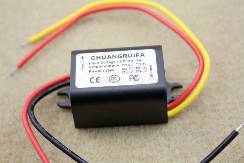
I make my own, takes 20 minutes of soldering & fully adjustable up to 2 volts less than the input voltage ( max 35V) Even housed in the same box but without the fancy sticker. Total cost $7
-
99.99% of RG59 cable problems are with the BNC terminations. The two most common ones are-
Strands of the braid not trimmed to length & are shorting out to the centre pin.
The centre pin not "locked in" when inserted into the outer body before crimping & so not long enough to make connection.
Determining which end is faulty is near impossible without a TDR. Just take a guess ( and usually be wrong). For basic testing I just use a multimeter & s/c termination at the far end.
-
For the analog component of system is their a bnc patch panel?]
Get a bit of aluminium & drill 10mm holes in it.
-
For large installations it's always going to be better to terminate on a patch panel for tidyness , cable management, flexibility of use and ease of maintenance
-
Yeah , people scoff at the old B/W cameras but you can't beat them for low light performance. For situations that don't require colour they are the way to go.
-
I want to build out a system for under $ 600 to start ( 4 cameras will add 4 more later )I need it to have decent quality for night / low light
Thanks
Depends what YOU call decent. For night/low light operation --- NO
-
If you have digital cable, forget about using a modulator.Finally, there is the upcoming switch from analog broadcast channels to digital. As TV manufacturers stop making sets with analog tuners, where will modulators fit in? Stay tuned.
Told you so
-
last time I looked digital modulators cost a motzaIs it pesach already ? My how time flies when yer having fun!
??????
-
last time I looked digital modulators cost a motza
-
1Vpp is only a nominal signal level & some cameras output less than this.
-
I thought RG6 was good stuff, what is the best?I didn't say it wasn't good stuff , I just said it wasn't the best for CCTV. RG6 has transmission characteristics designed for RF of approx 500 - 800 Mhz where as CCTV sub carrier is 5.5 Mhz. RG59u is designed for those lower frequencies
-
Normally the four cameras will be wired to a DVR or NVR which will multiplex the four cameras into one composite picture for viewing on screen. This can then be plugged into an A/V input on your TV or modulated to "appear" as a TV station signal in its own frequency slot. This second method has become difficult with the advent of digital TV.
BTW RG6 is not the best cable to be using for CCTV
-
i'm sorry, but that made no sense at all. do you know what punctuation is? sentences? it's not even clear what the actual problem/question is..
Same here but I do like a challenge & after reading it 8 times I took a guess at what he was asking.
-
am I reducing the signal this way I assume so due to the impeadence matching circuit of the one channel balun ????I am sure the blue stuff cat5 that is is of crap variety adding to the problem but anyway can I input the 1.5 to 1.75 volt video signal
directly into the active 2 wire ports on the balun it also has a 4 channel rs485 port will I burn up the active balun by trying this I just feel the signal loss on the input side of the active balun is really hurting me.
so I have one 8 channel passive balun head end and two active on the camera end...could use some guidance
Using a passive balun will result in a small amount of signal loss ( insertion loss )
You can insert the video signal directly into the transmit balun but the level is more likely to be 1 vpp NOT 1.5 to 1.75 V. 1Vpp is the nominal o/p level of a cctv camera.
-
Having power connections exposed to the elements is plainly stupid. There are some people who should stay away from DIY & pay someone instead.
-
Or install low watt motion lights - much better outcome than the IR.agreed , much much better.
-
When you say you mounted these cameras on 1/2" thick rubber it sounds like the mounting screwa/bolts just run through the bracket , through the rubber & onto the metal building. So if you think the rubber is insulating the cameras then you'd be wrong. Having said that , all full body cameras I've seen are insulated from the housing anyway. I have had similar problems on similar sites but they have usually been cured by using a UPS to "clean up " the mains voltage which can have huge spikes on it when 3 phase welders are in use
-
It is simply because the IR on those cameras is arranged as a "spot" instead of a "flood" light. This is a common problem on these cameras & can be overcome by disabling the IR on the camera & installing remote IR illuminators to give a flood light effect.
-
Can someone explain to me what a HDA is & what powers they have ?
What is the best way to distribute the CCTV signal?
in General Digital Discussion
Posted
Still haven't a clue whats going on here.